Modifications
Please remember that any modifications you undertake are entirely at your own discretion. While we aim to offer helpful guidance, we cannot assume responsibility for any resulting damage, injury, or loss. Proceed only if you feel confident in understanding the process and accept the associated risks
- Common Modifications
- Belt Drive Drum Mod
- Solderless Artisan Installation
- Vented Electronics Enclosure
- Thermocouple Mod
- Skywalker V1 HiBean Firmware Installation
- Skywalker V2 HiBean Firmware Installation
- V1 to V2
- Cubean
- V1 Worm Drive Mod
Common Modifications
Common Mods Easy
- bend off mean chute lip
- 3d printed chute
Med to Hard
- Artisan Mod
- Uno R4 comment out the timerinterrupt it's actually not being used
Belt Drive Drum Mod
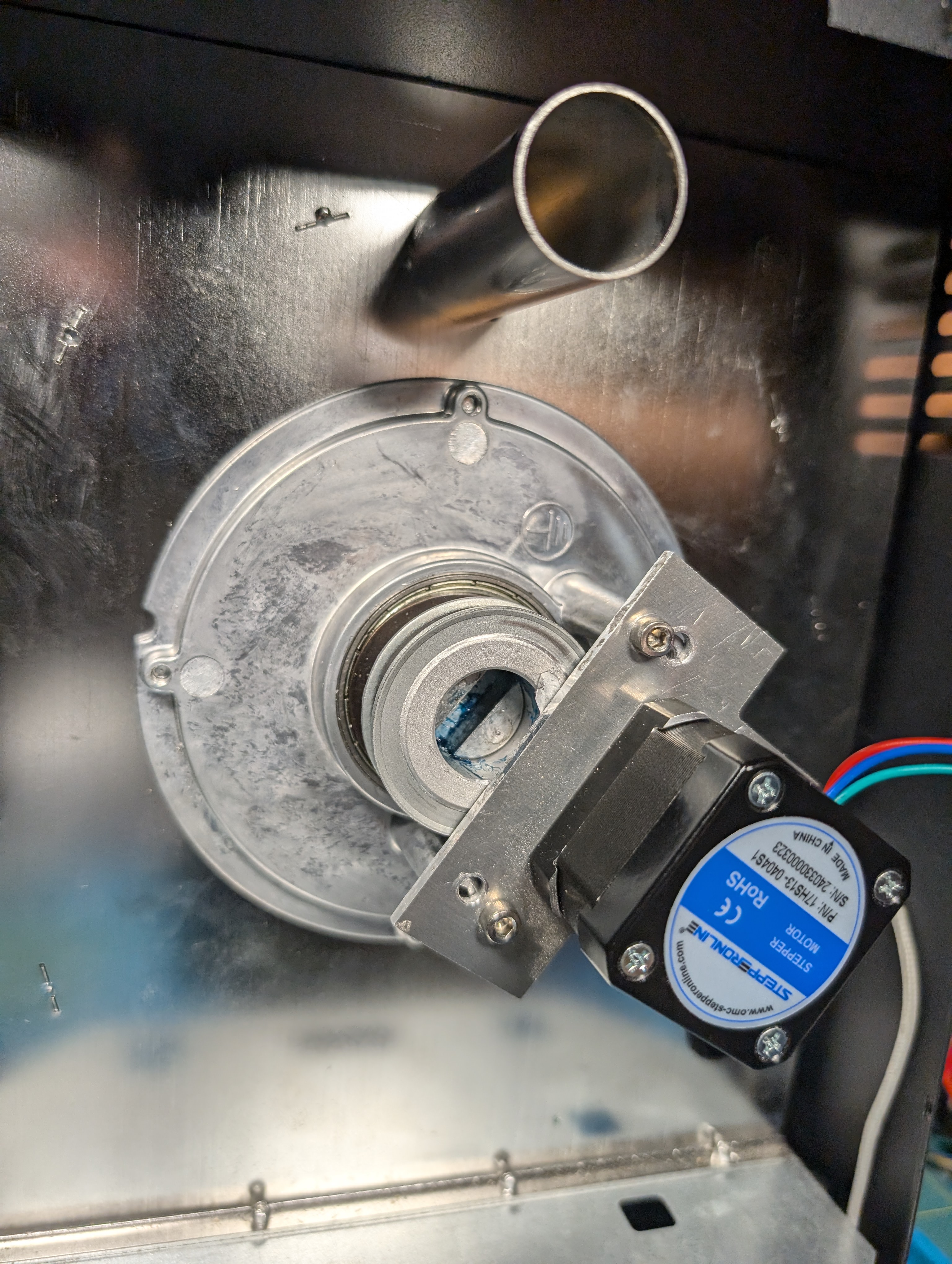
Fits with modified electronics box. Quieter than stock RPM controllable via Artisan.
BOM:
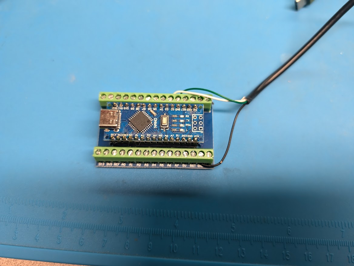
| Arduino Nano | $6 | |
| Nema 17 34mm Body | $12 | LDO 42STH34 |
| Driver 2209 | $7 | 2209 may work with 5160 |
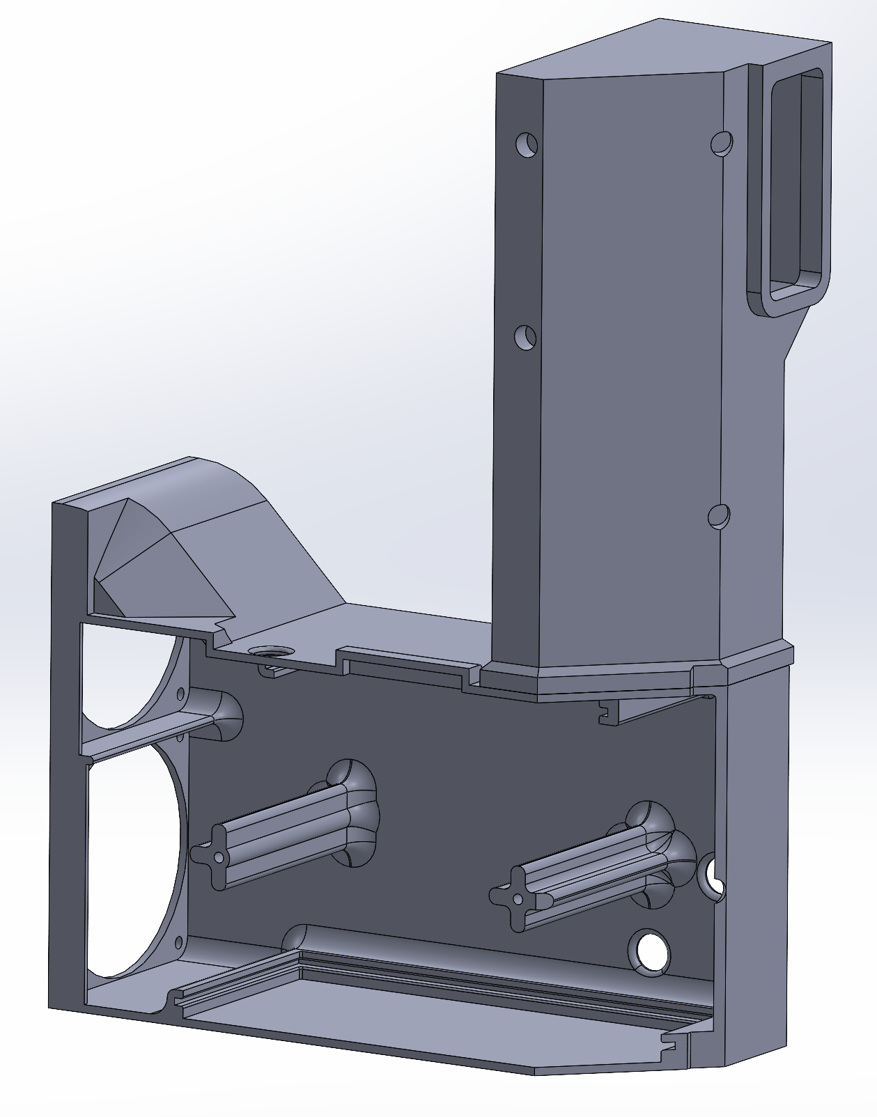
| Custom Bracket | $9 | 6061 Alu plate 3mm thick Drilling Required |
| 20t Pulley | $2 | 6mm bore 6mm wide belt |
| 60T Pulley | $10 | 20mm Bore 6mm wide belt |
| 164mm Close Loop Timing Belt | $4 | 164mm GT2 belt |
Solderless Artisan Installation
| BOM | QTY |
| Arduino Nano | 1 |
| Arduino Nano Terminal | 1 |
| USB Cable | 1 |
Follow these instructions:
Skycommand
Install Video
Livestream Install

Vented Electronics Enclosure
This 3D printed Enclosure was made by the Discord user LookattheGeeks
File:
CHIMNEY_V4.3MF
Installation (partial):
Nirecue Stream
Thermocouple Mod
Hardware Components You’ll Need:
- Arduino Nano
- HW-550 Thermocouple (MAX6675) Module
- Jumper Wires
- USB Cable for Arduino Nano connection
- TCSkycommand.ino
Quick Video Overview
Step 1: Installing the Arduino IDE
If you haven’t already installed the Arduino IDE, follow these steps:
- Download the Arduino IDE from the official Arduino website.
- Install the software on your computer, following the on-screen instructions for your operating system (Windows/macOS/Linux).
- Once installed, open the Arduino IDE.
Step 2: Installing the MAX6675 Library
To interface with the HW-550 (MAX6675) thermocouple, you will need the MAX6675 library.
- Open the Arduino IDE.
- Click on Sketch > Include Library > Manage Libraries.
- In the Library Manager window, type MAX6675 in the search box.
- Look for the library titled MAX6675 by Adafruit and click Install.
- Wait until the installation is complete.
Step 3: Wiring the HW-550 (MAX6675) to Arduino Nano
Hardware Setup
-
Thermocouple (MAX6675) Connections: The code sets these pins:
pinSCK = 7pinCS = 6pinSO = 5
Wire your MAX6675 module as follows:
- Arduino
5Vto MAX6675VCC - Arduino
GNDto MAX6675GND - Arduino
7 (SCK)to MAX6675SCK - Arduino
6 (CS)to MAX6675CS - Arduino
5 (SO)to MAX6675SO
Note: If your MAX6675 module specifies different power requirements or has a regulator onboard, ensure you follow its recommended wiring.
-
Roaster Control Lines:
txPin = 3(Arduino output)rxPin = 2(Arduino input)
Connect these pins to your roaster's control interface as required. These pins are used for sending and receiving signals from the roaster.
-
Power and Grounding: Ensure all grounds (Arduino, MAX6675, roaster interface) share a common ground. Double-check all connections to avoid damage to the board or sensors.
Preparing the Code
-
Open Arduino IDE: Launch the Arduino IDE on your computer.
-
Create or Open the Sketch:
- Create a new sketch (File > New).
- Copy and paste the provided code into the new sketch window.
-
Select Your Board and Port:
- Go to Tools > Board and choose your Arduino board model (e.g., Arduino Uno).
- Go to Tools > Port and select the port that your Arduino is connected to.
-
Verify Libraries:
- Ensure the
MAX6675library is installed via the Library Manager as noted above. SPIis included by default, no additional steps needed
- Ensure the
Compiling and Uploading
-
Verify (Compile) the Code:
- Click the Checkmark (Verify) button in the Arduino IDE toolbar to compile the code.
- If there are errors, make sure you’ve selected the correct board, port, and have the MAX6675 library properly installed.
-
Upload the Code:
- Once verification is successful, click the Right Arrow (Upload) button to upload the code to your Arduino.
- After upload completes, the Arduino will reset and begin running the program automatically.
Running and Interacting
-
Serial Monitor:
- Open the Serial Monitor by going to Tools > Serial Monitor.
- Set the baud rate to
115200to match the code’s setting.
-
Commands: You can send commands via the Serial Monitor. Examples:
READ— returns the temperature readings and current duty cycles.OT1;XX— sets heater duty cycle to XX (0-100).OT2;XX— sets fan duty cycle to XX (0-100).DRUM;1— turns the drum on (100%),DRUM;0turns it off.FILTER;XX,COOL;XX— sets filter fan or cooling levels.CHAN— responds with channel setup.UNITS;CorUNITS;F— changes temperature units between Celsius and Fahrenheit.OFF— shuts down all outputs.
-
Data Output:
- The Serial Monitor will display temperature data from the thermocouple and any status messages.
- If no commands are received for an extended period, the code will shut everything down for safety
Troubleshooting
- No Temperature Reading:
Double-check thermocouple wiring and confirm the MAX6675 module is functioning. - No Response to Commands:
Ensure you’ve set the correct baud rate and are typing commands properly in the Serial Monitor. - No Upload / Compilation Errors:
Confirm you have the correct board selected and libraries installed.
-
Please remember that any modifications you undertake are entirely at your own discretion. While we aim to offer helpful guidance, we cannot assume responsibility for any resulting damage, injury, or loss. Proceed only if you feel confident in understanding the process and accept the associated risks
Thank you TOU! for providing code which can be seen on kaffee-netz.de forum.
Skywalker V1 HiBean Firmware Installation

Pre-Requisites
This is still in Beta and code is still being worked on. Please report any issues you have to our Community Discord.
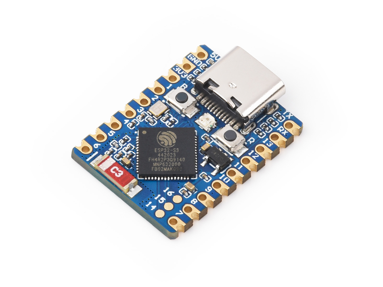
- A supported ESP32 device: Ensure you have a supported ESP32 device, such as the Waveshare ESP32-S3 and a USB cable. The S3 is a compact, low-cost device which can plug directly into the v1 Skywalker using a USB-C <-> USB-A adapter or suitable A to C cable.

- A suitable "Community" Binary File to flash onto the esp32 device: Latest Community Binaries
- A Browser for flashing the binary: Use Google Chrome or Microsoft Edge (supports Web Serial) ESPHome.
- USB Cable: A reliable cable for data transfer.
Steps
1. Download the appropriate Binary File
- There a are a few community binary authors, but generally you should use the latest release from any of:
- Download the .bin file that's appropriate for your particular esp32, and save it to a location which you can easily find later.
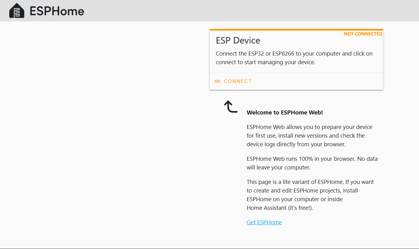
2. Open ESPHome Web
- Go to ESPHome Web in your Chrome or Edge browser.
- Connect the ESP32 to your computer using a USB cable or adapter.
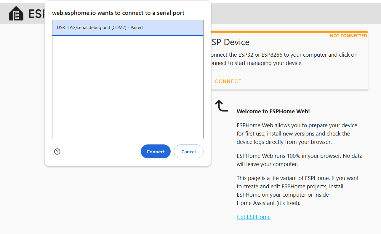
3. Connect to the ESP32-S3
- On the ESPHome Web page, click the Connect button.

- A pop-up will appear with available devices. Select the port for your ESP32-S3 and click Connect. This will generally show as a "USB JTAG/serial debug unit" on a COM port on Windows, or on /cu/usbmodem port on MacOS. If your device does not appear here, or appears and disappears repeatedly, see Troubleshooting below.

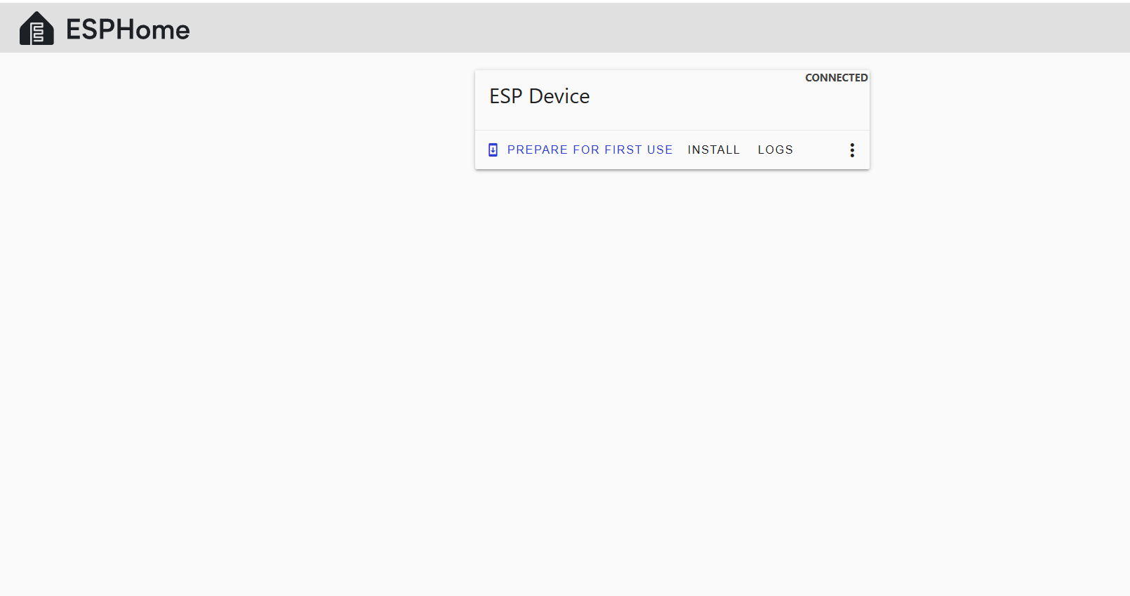
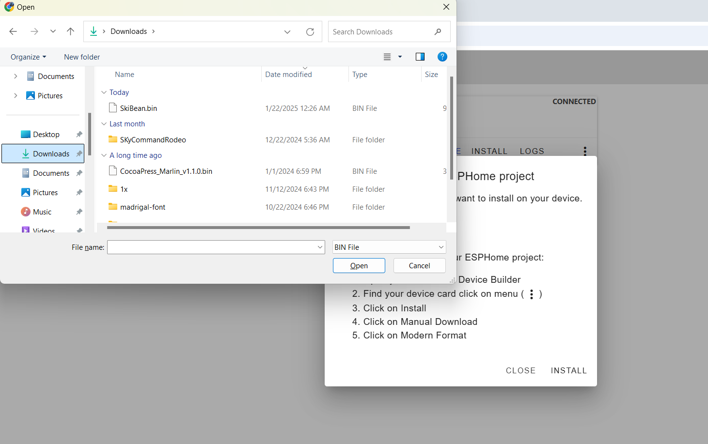
4. Install the Binary File
- Once connected, click Install.

- Choose File when prompted
- In the file selection dialog, locate and select the firmware .bin file you downloaded earlier.

- Click Install to start the flashing process.
-


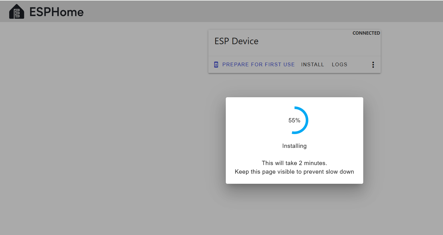
5. Flash the Firmware
- ESPHome Web will erase the existing firmware and flash the
SkiBean.binbinary.

- The flashing process may take a few minutes. Wait for it to complete.
- After successful installation, a success message will appear.

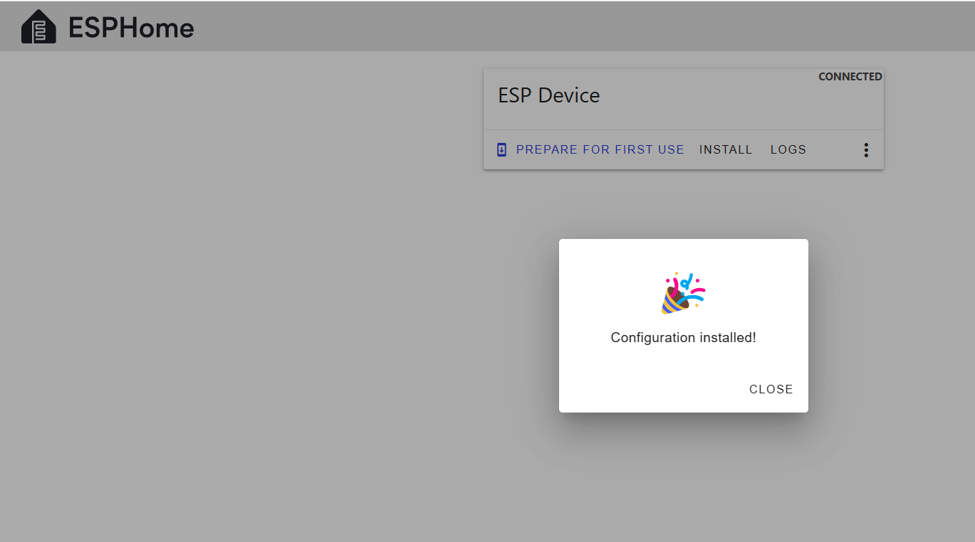
6. Visual Test
If all goes well, you should see an LED on the ESP32 begin to flash alternately red/blue. If so, that means your esp32 flashed successfully.
- If not, momentarily unplug and replug the ESP32 from the USB port. After a few seconds, the LED should start flashing. If not, something is wrong. Ask on Discord.
- If so, you can now plug the ESP32 into the back of the Skywalker.
7. Connect from HiBean
- Start your HiBean app, and click (+) in the upper right to add a new roaster.
- Scroll down and select Skywalker
- In there select the "Skywalker Comm" (for Community) - the HB is for the official HiBean Skywalker Controller which can be purchased if you don't wish to flash your own device.
- Happy Roasting!
Troubleshooting
- Device Not Recognized: Ensure your USB cable supports data transfer.
- Flashing Errors
-
Hold BOOT and press RESET (recommended method):
- Hold down the BOOT button.
- While holding BOOT, press and release the RESET button.
- Continue holding BOOT for a second, then release it.
-
-
-
Unplug and replug while holding the BOOT button:
- Disconnect the ESP32-S3 from power (USB).
- Press and hold the BOOT button.
- While holding BOOT, plug the USB back in.
- Once connected, release the BOOT button.
-
- Let me know if you encounter issues or need further help!
Skywalker V2 HiBean Firmware Installation
Requirements
This is still in Beta and code is still being worked on. Please report any issues you have to our Community Discord.
- ESP32-S3: Ensure you have the ESP32-S3 board and a USB cable.
- Power Data Y Cable

- Binary File Link:
Bear - Browser: Use Google Chrome or Microsoft Edge (supports Web Serial) ESPHome.
Steps
1. Download the Binary File
- Open the GitHub link: TBA
- Click on the download raw file icon to download

2. Open ESPHome Web
- Go to ESPHome Web in your Chrome or Edge browser.
- Make sure your ESP32-S3 is connected to your computer using a USB cable.
3. Connect the ESP32-S3
- On the ESPHome Web page, click the Connect button.
- A pop-up will appear with available devices. Select the port for your ESP32-S3 and click Connect.
4. Install the Binary File
- Once connected, click Install.
- Choose File when prompted
- In the file selection dialog, locate and select the
SkiBean.binfile you downloaded earlier.
- Click Install to start the flashing process.
-
5. Flash the Firmware
- ESPHome Web will erase the existing firmware and flash the
SkiBean.binbinary.
- The flashing process may take a few minutes. Wait for it to complete.
- After successful installation, a success message will appear.
Direct Link to Binary File
Troubleshooting
- Device Not Recognized: Ensure your USB cable supports data transfer.
- Flashing Errors
-
Hold BOOT and press RESET (recommended method):
- Hold down the BOOT button.
- While holding BOOT, press and release the RESET button.
- Continue holding BOOT for a second, then release it.
-
-
-
Unplug and replug while holding the BOOT button:
- Disconnect the ESP32-S3 from power (USB).
- Press and hold the BOOT button.
- While holding BOOT, plug the USB back in.
- Once connected, release the BOOT button.
-
- Let me know if you encounter issues or need further help!
V1 to V2
Upgrading from V1 to V2
Drum Motor
How to connect and code for a nano or ESP32 to control the motor.
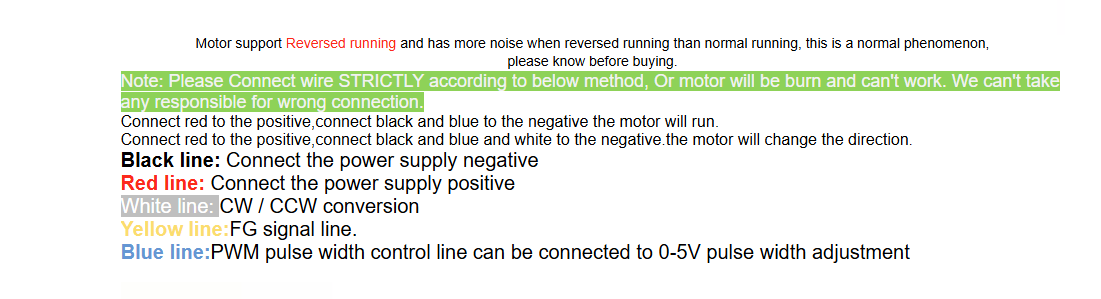
| Motor Wire | Arduino |
|---|---|
| Blue (PWM) | D6 |
| White (DIR) | D7 |
| Red (V+) | 12–24V |
| Black (GND) | Shared GND with Arduino |
1. Add These Pin Definitions at the Top:
const int drumPwmPin = 6; // PWM pin (connect to Blue wire)
const int drumDirPin = 7; // Direction pin (connect to White wire
2. Add These to setup():Make sure these lines are inside your setup() function
3. Replace Your handleDRUM() With This Version:
void handleDRUM(uint8_t value) {
if (value > 100) value = 100; // Clamp value to 100
int pwmValue = map(value, 0, 100, 0, 255); // Scale 0-100 to 0-255
if (value != 0) {
digitalWrite(drumDirPin, HIGH); // Set motor direction (HIGH = CW)
analogWrite(drumPwmPin, pwmValue); // Apply PWM speed
setValue(&sendBuffer[drumByte], value); // Update protocol buffer
} else {
analogWrite(drumPwmPin, 0); // Stop motor
setValue(&sendBuffer[drumByte], 0);
}
lastEventTime = micros();
}
Cubean
Cubean TX Protocol (Controller → Roaster)
-
Direction: Arduino/controller → Cubean roaster
-
Rate:
9600 baud, 8 data bits, no parity, 1 stop bit (SERIAL_8N1) -
Interval: Sent every ~200ms
-
Packet Length: 11 bytes
-
Structure:
| Byte Index | Hex | Meaning |
|---|---|---|
| 0 | FE | Start byte 1 |
| 1 | EF | Start byte 2 |
| 2 | 00 | Unused/reserved |
| 3 | 00 | Unused/reserved |
| 4 | 5A | Drum/Cooler/Fan state (bitfield?) |
| 5 | 64 | Heat power (0–100 decimal) |
| 6 | 02 | Unknown, possibly a mode ID |
| 7 | 76 | Fan speed (0–255 scale) |
| 8 | AA | Marker |
| 9 | 55 | Marker |
| 10 | 22 | Checksum or end byte |
Cubean RX Protocol (Roaster → Controller)
-
Direction: Cubean roaster → Arduino/controller
-
Rate: Same UART config:
9600 baud,SERIAL_8N1 -
Interval: ~200ms
-
Packet Length: 11 bytes
-
Structure:
| Byte Index | Hex | Meaning |
|---|---|---|
| 0 | FE | Start byte 1 |
| 1 | EF | Start byte 2 |
| 2 | 0X | Temperature high nibble (BCD/hex?) |
| 3 | YY | Temperature low nibble |
| 4 | 00 | Unknown |
| 5 | 00 | Unknown |
| 6 | 00 | Possibly status byte |
| 7 | 00 | Possibly another status byte |
| 8 | AA | Marker |
| 9 | 55 | Marker |
| 10 | XX | Checksum or data byte |
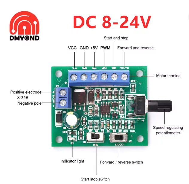
V1 Worm Drive Mod
BOM
PWM Motor Board
https://www.aliexpress.us/item/3256804512610220.html
Worm Drive Motor JGY 28-38 24V 96RPM
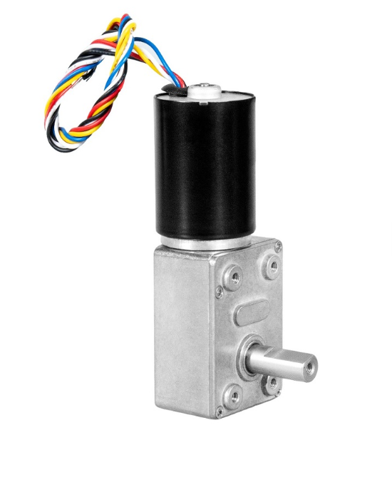
Custom Motor Mount (DXF coming Soon)
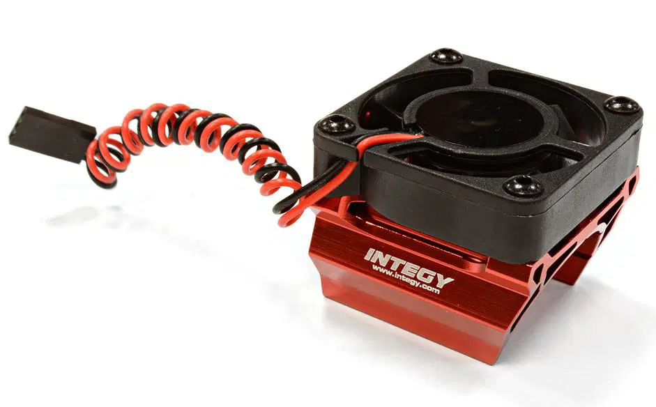
Motor cooling Fan
*Double check Discord on newest recommendation
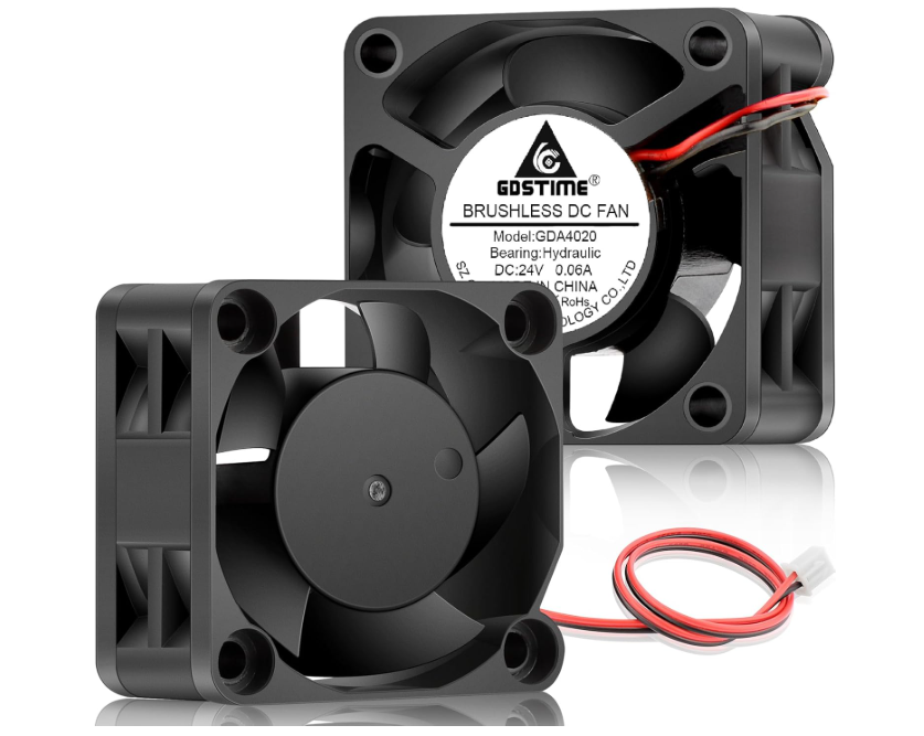
Optional:
28mm heat sink and associated 24 fan